


Overview of HDPE pipe inspection
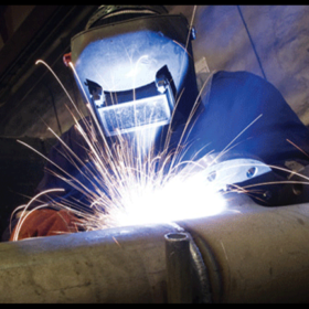
Normally, builders often use four methods to conduct welding HDPE pipe because the easy way to do it is: Heat butt welding method, Coupling welding method, Resistance welding method, Rubber gasket jointing method. Among them, the method heat butt welding is the most popular method due to its good penetration and simple welding technique.
High-density plastic (HDPE) pipes have been used to replace steel pipes in the petrochemical, energy and mining industries due to their corrosion and erosion properties. More recently, HDPE has also been used in nuclear power plants in applications involving chilled water to maintain safety. Nuclear applications require safety guarantees at the connections. Ultrasonic time-of-flight diffraction (TOFD) is commonly used for structural integrity of these thermobaric welds.
Problems to be solved when ultrasonic inspection of HDPE pipes
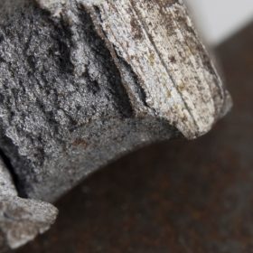
HDPE joints often have one common type of defect: no wall penetration, internal defects and holes. In the present industry there is no universal standard to manage the size of the largest defects, however, non-destructive testing is often used or required to check the condition of these joints.
HDPE material has some special properties that make inspection difficult. The acoustic impedance and speed of sound waves are very similar to those used in the manufacture of ultrasonic test fittings, making obtaining a suitable beam angle of resistance requires specific setups and equipment. In addition, the junction between Rexolite and the HDPE material may encounter problems due to the incompatibility of acoustic impedances. Furthermore, HDPE is a relatively sound-dispersive and absorbent material compared to steel, so conventional high-frequency transducers cannot be used. To eliminate these difficulties, low frequency TOFD probes and TOFD water wedges should be used.
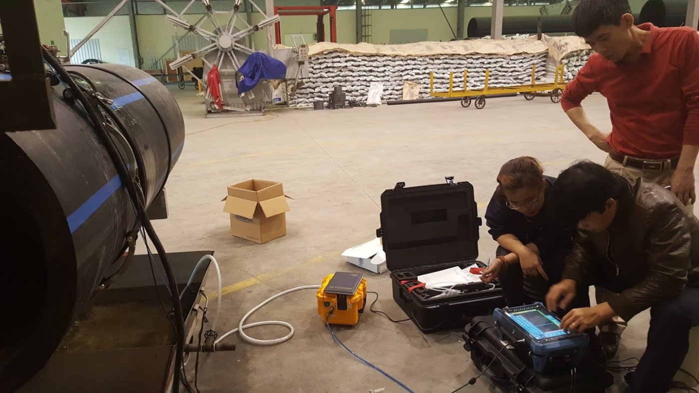
The main equipment for testing the welds of HDPE pipes
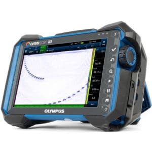
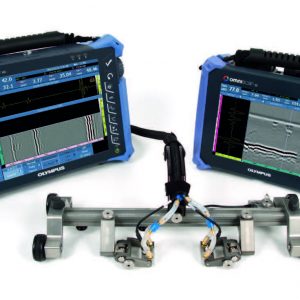
PV-200 system is based on 2 techniques Supersonic is Time of Flight Diffraction (TOFD) and Phased. While TOFD is a fast, relatively efficient technique that detects defects of any orientation and shape and is capable of accurately sizing defects, TOFD has inherent limitations in certain areas. near the top and bottom of the material. The Phased Array perfectly complements these limitations and also provides other information that makes the assessment of defects much simpler and more accurate. The PV-200 solution is often used to replace traditional radiography or ultrasound.
The complete system includes:
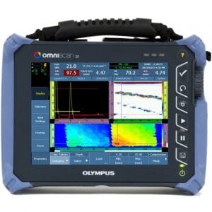
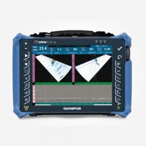
- OmniScan MX2 with 16:128 . ultrasound module
- ChainScanner chained probe holder.
- Water pump use to supply CFU03 junction or use hand pump
Accessories for TOFD inspection:
- 0.5 m splitter cable for PA transducers and 4 UT channels (P/N: E128P0-0202-OM)
- TRPP-5810 2-channel pulser/preamplifier (P/N: TRPP-5810)
- TOFD and wedge probes (see details in table below)
- UT cable for TOFD . probe
- 5 m UT RG174 coaxial cable with LEMO-00 to LEMO-00 connectors (P/N: C174-LM-LM-5M)
- 5 m UT RG174 coaxial cable with LEMO-00 to Microdot connectors (P/N: C174-LM-UDOT-5M)
- 0.45 m UT RG174 coaxial cable with LEMO-00 to Microdot connectors (P/N: C174-LM-UDOT-0.45M)
Experimental inspection of some samples of HDPE pipe welds
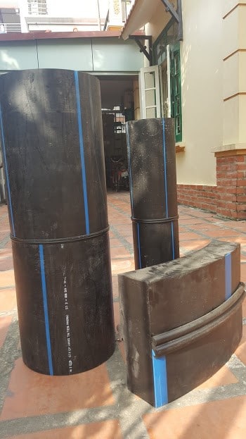
The test was carried out on 3 pipe samples, on samples with false defects using 2mm and 3mm drill holes. The results were tested multiple times to determine repeatability and reliability. The reagent in the experiment was water, supplied continuously using a hand pump system.
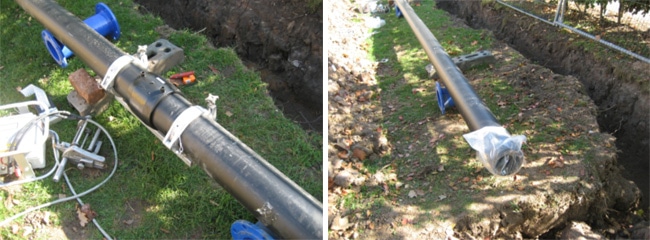
During the test, the pipes with irregular round diameters or eccentricity when connecting as well as the location near the joints with uneven surfaces slow down the test work due to the transducer being out of position. It is therefore necessary to use a larger probe holder with suitable wheels.
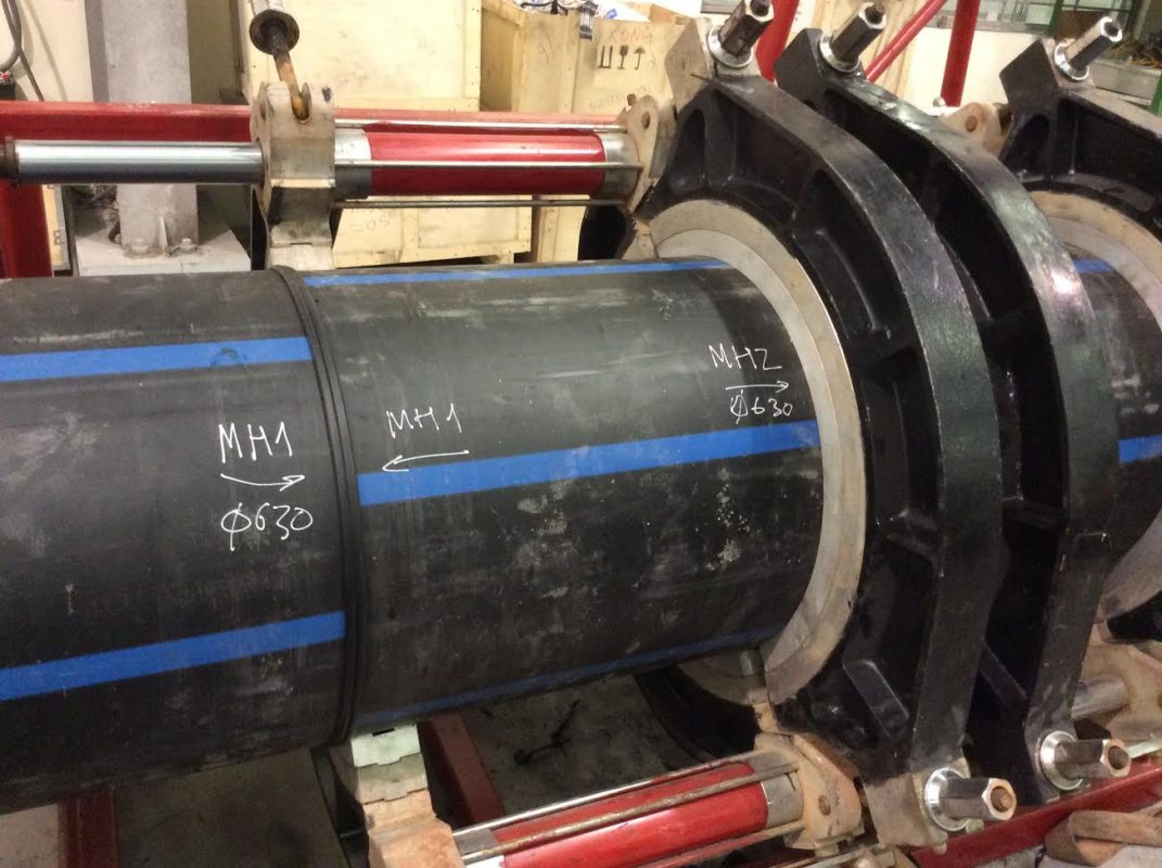
HDPE weld pattern No. 1
Large pipe, wall thickness 20mm, diameter 300mm (Sample 1). There are 2mm and 3mm drill holes at about 50mm, 100mm, 350mm and 850mm to fake the flaw in the non-crushing position of the weld.
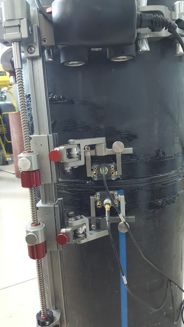
Model 1 has a circumference length of about 900mm. Scan test at 1300mm length to show repeatability of test results (900-1300mm is the result of 2nd scan repeated at the end of 1 circumference of first 100-400mm).
Test on sample 1, using a chain-link ChainScanner to hold the probe and make it easy to move around the tube. Probes used tested use both 2MHz and 5Mhz types. The water wedge creates an angle of 70 degrees, the probes are placed 50mm apart. Focus the acoustic beam at 15mm so that both near-surface and subsurface weld defects can be detected.
HDPE weld sample No. 2
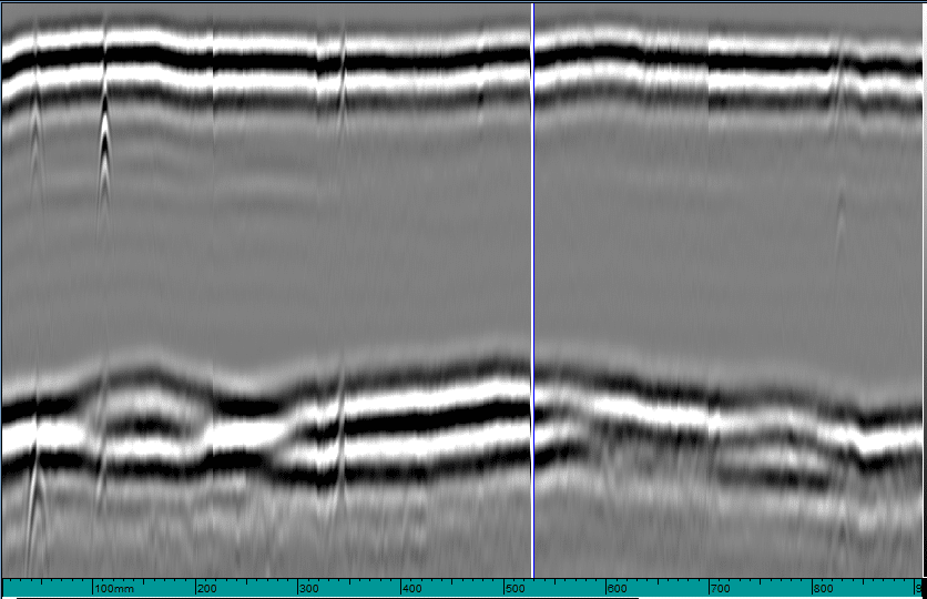
Small pipe, wall thickness 15mm, diameter 170mm (Model 2). There are 2mm drill holes at 30mm and 140mm to fake the non-fusion position of the weld.
Model 2 has a circumference length of 530mm. Test scan at 800mm length (repeat scan at end of circumference) to show repeatability of test results.
Test on model 2, using the chain-link ChainScanner to hold the probe and make it easy to move around the tube. Probes used tested use both 2MHz and 5Mhz types. The water wedge creates an angle of 70 degrees, the probes are placed 50mm apart. Focus the acoustic beam at 11mm so that both near-surface and subsurface weld defects can be detected.
3 . HDPE weld sample
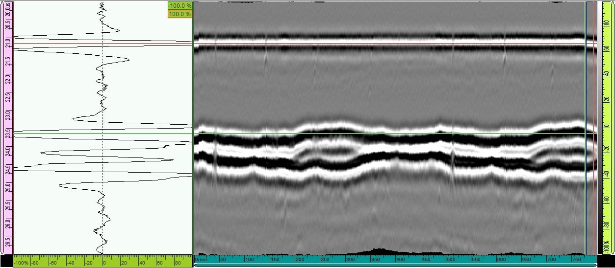
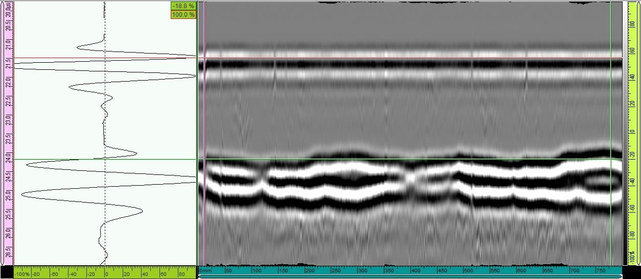
Large pipe, cut into pieces, wall thickness 100mm, diameter unknown (Sample 3). There are drill holes at 150mm and 300mm positions and horizontal drill holes at both ends of the pattern.
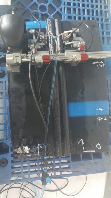
Test on model 3, using the chained ChainScanner scanner. Probes use test using both 2MHz and 5Mhz types and 70, 60, 45 degree wedges to test different thicknesses. Due to the large size of the weld cap area of 70mm, the probes are spaced at least 70mm apart and can make the detection of small defects near the surface more difficult.
The cutting size of sample 3 is also small and there is not enough space to arrange the probe and scanner, so it is not possible to arrange a 45-degree probe to focus in the deeper area of the weld (75mm). .
Test results of HDPE pipe welding
Sample test results 1
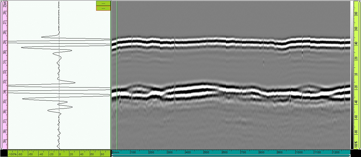
In both scans, all defects were detected. Repeatable data can be observed from 0 and 900mm positions. On the data all 4 defects can be observed. In the repeat segment, defects 1, 2 and 3 can be observed.
The 2mm holes have a smaller response margin than the 3mm holes. Therefore, a signal preamplifier can be used to give clearer results.
Sample test results 2
Because of the small tube, surface conditions have a greater influence on Lateral waves (surface waves). Therefore, the test results use the surface pulse synchronization feature to "iron" flat, which helps to better observe defects. Notice that the roughness of the surface has been treated flat.
The 15mm sample when using the 5Hz probe gives better results, the defects are more obvious. Therefore, in tests of thin tubes less than 20mm, a high frequency transducer should be used. The results will be even better if combined with a preamplifier.
3 . sample test results
Due to the small size of sample 3, there is not enough room to arrange the probe in the optimal position (Probe placed far from the junction to catch bottom pulses and near-bottom defects). Test results include results from 5MHz probe, 70mm wedge spaced 70mm and 2MHz probe, 60 wedge spaced 70mm apart.
Results when using a 5MHz probe to detect near-surface defects (0-30mm).
2MHz detects mid-zone defects (30mm-60mm)
Resistance welding test for HDPE pipes
Resistance welding is the name given to welding using resistance implants of flexible plastic tubes. It is one of the two main techniques used to join polyethylene water pipes, and is one of the most reliable methods of joining plastic pipes when pipes need to be subjected to high pressure.
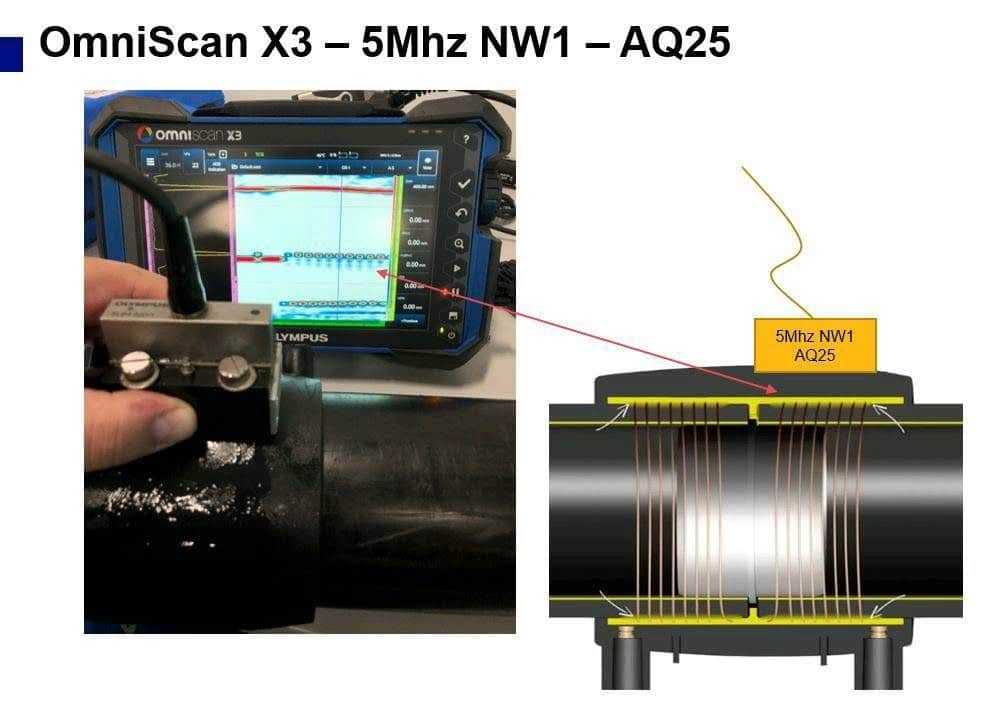
The electric welding process involves the use of a coupling tube containing a resistance coil that can be heated by supplying electricity. The pipe ends are prepared and put into the coupling part and fixed. A current is then passed through the coil for a pre-calculated time depending on the tube thickness. The polymer around the coil is heated and transfers heat to the wall of the tube. The cold zone is at the ends of the coupling and the fusion and melting zone is in the center, allowing for higher melting pressure and uniform joint formation.
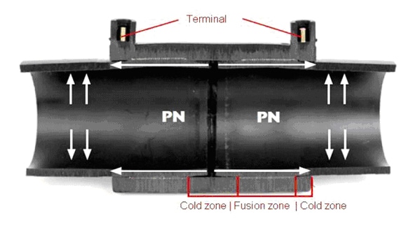
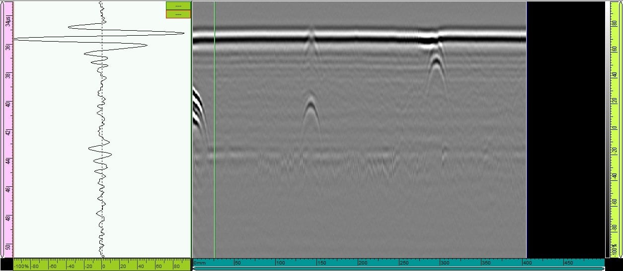
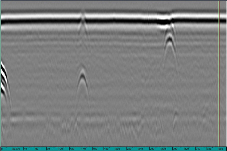
The commonly used resistance welding test for HDPE pipes probe NW1 has good surface resolution for composite materials, combined with water wedge SNW1-0L-AQ25. The signal is focused at depth around the coil, which gives good resolution and can easily detect separation/failure between the tube and coupling.
Conclusion
- The test plan that can catch relatively small defects is 2mm and 3mm drill holes in the position of the weld. Actual defects can be much larger and easier to catch since the edges of the defects are sharp and give better feedback than man-made defects that are drill holes.
- In fact, artificial defects created on welding samples can be detected well, at a fast rate.
- The defects appear clearly, with high repeatability. It is suggested that when checking in reality, it is possible to double check the circumference so that the data repeats 2 times.
- When testing thick samples, probes with different frequencies and angles help confirm defects. However, it is necessary to use an optimal frequency and angle probe for best results.
- For welds of 50mm or more, it is possible to combine 2 or 3 probes at the same time to avoid the case that one probe can only focus on one area of the weld. When planning the inspection, it is necessary to draw the Beam Profile and calculate the beam extension to avoid missing defects.
- Can be combined with Phased Array when you want to study more deeply about defects (Shape, orientation... or when you need to perform more complex applications such as resistance welding).
- The separation testing solutions in HDPE near the joint can be combined if required by the standards.
- When doing field testing with large thickness samples, it is necessary to use scanners that support 2-3 channels (6 probes) at the same time to ensure data uniformity and save time.
Equipment used in the article
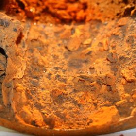
Corrosion test
Corrosion test
Measure thickness