


We are familiar with medical 3-D color ultrasound examination applications, where high-frequency sound waves are used to produce highly detailed cross-sectional images of internal organs. Medical ultrasound is usually performed using specialized multi-element probes called Phased Array or Phased Array probes with accompanying hardware and software to build and display images. But the applications of technology Ultrasound Phased Array not limited to medical diagnosis. In recent years, phased array ultrasound systems have been increasingly used in industrial applications to provide information and visualization in ultrasound tests such as weld inspection, thickness quantification and crack detection. This article briefly introduces the operation of phased array ultrasonic systems and their applications in industrial non-destructive ultrasonic testing.
Ultrasonic phased arrays are used for a wide variety of measurement and inspection applications, for any job done with conventional ultrasound. For example, PAUT is used to detect and visualize defects such as crack, void and corrosive. They are used to material thickness measurement and coatings, and detect changes in material properties. Another popular app is weld quality assessment and rivet.
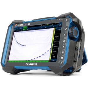
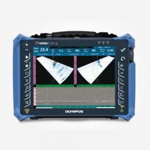
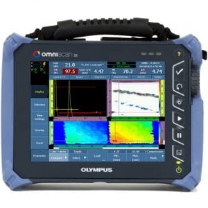
What does the PAUT ultrasound device include?
Conventional ultrasonic transducers for NDT inspection applications typically consist of a single active element to both generate and receive high frequency sound waves, or two, one to transmit and one to receive the signal.
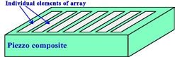
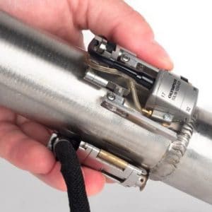
Phased array ultrasonic transducers, usually consisting of a probe assembly with the word 16 to up to 256 individual elements that each element can be independent trigger and pulse. They can be sort by a range (linear array), a ring (annular array), a circular matrix (circular array), or a more complex shape. As is the case with conventional probes, phased array probes can be designed for direct contact use, using wedges for angle, or for use embedded test domestic.
Most common PAUT probe frequency in the range 2 MHz to 10 MHz. A phased array ultrasound system will also include a computer capable of controlling the multi-element transducer, receiving and digitizing the feedback signals, and plotting the feedback information using different formats. different display. Unlike conventional flaw detectors, phased array systems can scan the sound beam through a series of refraction angles (fan scan) or along a linear line (linear scanning), or focus the beam at a specified depth, thereby increasing both flexibility and functionality in test setups.
Principle of ultrasonic testing PAUT
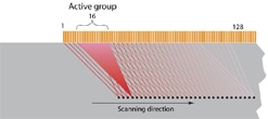
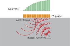
Basically, one phased array ultrasound system uses the physics principle of acoustic wave beam divergence, varying the time between a sequence of ultrasonic pulses, and controlling them so that they travel in such a way that individual wavefronts are produced by each element in the resulting array. together to enhance or cancel energy in a predictable manner, thereby directing and shaping the sound beam. This is done by exciting independent transducer elements at slightly different times.
Normally, the variables will be group control from 4 to 32 elements to effectively improve sensitivity by increasing aperture, reducing unwanted side-beam propagation and allowing better beam convergence.
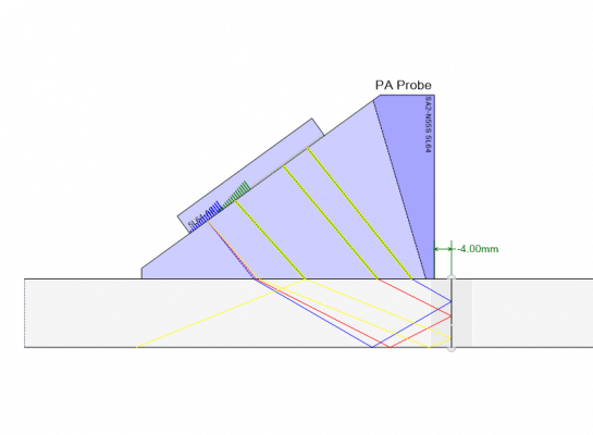
The Focal laws set up a specific delay for transmitting each group of elements to produce the desired beam shape, taking into account the characteristics of the probe and wedge as well as the geometry and acoustics of the test material. Wavefronts form one after another combine to enhance or cancel and form a wavefront uniquely propagates through the test material and reflects off locations of cracks, discontinuities, material bottoms, and other material boundaries. Just like regular ultrasound.
Factors affecting the beam produced
The beam can be dynamically controlled over various angles, focal distances and focal point sizes so that a The only probe that can test the test material on many different angles. This beam navigation is very fast, so scanning from multiple angles with multiple focal depths in a fraction of a second can be performed.
The beam can only focus in the near field, and the more elements are used, the more concentrated the energy can be focused, thereby increasing the beam quality and reducing the SNR ratio.

10 variables 16 variables 
32 variables
The returned reflected pulses are received by different elements or groups of elements and are time-delayed calculated to compensate for the different wedge delays and summed. Unlike conventional single-element transducers, phased array probes can sort the return wavefront distance according to arrival time and amplitude at each element. When processed by software, each convergence law returns a reflection from a specific angle of the beam, a specific point along a line, and a reflection from a depth with a specific focal length. The reflected pulse information can then be used displayed in different representations.

Linear scan mode 
Convergence law creates angle beam
Commonly used broadcast mode
Acoustic beam linear scan
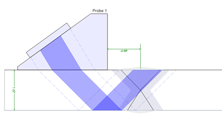
- Allows the sound beam to move along the transducer without moving the transducer u
- The All sound beams have the same emission angle with position change due to use different groups of variables.
- Similar to raster scanning in traditional ultrasound, but performed by electrical signals instead of mechanical
Scanning beam fan
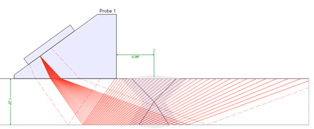
- Capable of scanning a large area without changing the probe position.
- Useful when inspecting objects with complex shapes and limited access.
- Sound beam has Various shooting angles are from same group of variables.
Linear play mode
See more articles Matters needing attention when planning weld inspection.
Image representation in Phased Array test
In most thickness measurement and flaw detection applications, ultrasonic inspection data will be based on amplitude and time information obtained from processed RF waveforms. These waveforms and the information extracted from them will typically be presented in the form of A scan, B scan, C scan, or S scan. The following section will introduce some examples of how to display images from both conventional defect ultrasound equipment and phased array ultrasound systems.
Image displayed in A-Scan . format
A-Scan is a simple RF waveform representation showing the time-amplitude correlation of an ultrasonic signal, commonly used on conventional ultrasonic flaw detectors and thickness gauges. waveform display. The sweep waveform A is used to represent the reflection from a beam position in the test specimen.
The A-scan ultrasound image below shows pulses reflected from two boreholes inside a steel sample block. The linear acoustic beam from a conventional single-element contact transducer is intercepted by two of the three boreholes and produces two distinct reflections at different times proportional to the depth of the hole.

Normal beam 
Straight probe A-Scan image Angle probe beam Angle probe A-Scan image
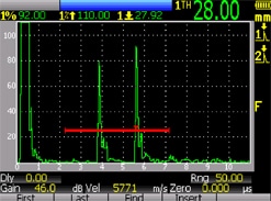
Single element angle beam detectors used with conventional flaw detectors will produce a beam of a definite angle. While beam propagation effects will cause the beam diameter to increase with distance, the coverage or field of a conventional angular beam remains essentially confined to a particular angular line. In the example above, a 45 degree wedge at a fixed position can detect two of the holes drilled inside the test specimen block because they are in the beam, but the third hole cannot be detected otherwise. move the probe forward.
A phased array ultrasound system will display similar A-scan waveforms for reference, however in most cases they will be supplemented by a B-scan, C-scan or S-scan as specified. see below. These standard image formats assist the operator in visualizing the type and location of defects in the test specimen.
Image displayed as B-Scan
The B-scan is a cross-sectional view of a longitudinal slice of the specimen, showing the depth of the reflections relative to their axial position. B-scan imaging requires the sound beam to be scanned along the selected axis of the specimen, mechanically or electronically, while storing the relevant data.
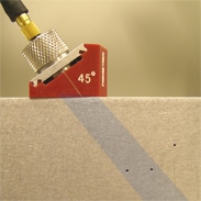
In the case below, the B-scan shows two deep reflections and one shallower reflection, corresponding to the positions of the boreholes inside the test block. With conventional flaw detectors, the probe shall be moved across the test piece.

Straight beam 
B-Scan image
On the other hand, a phased array system can use electronic scanning along the length of a linear array probe to create a similar cross-section without moving the probe.
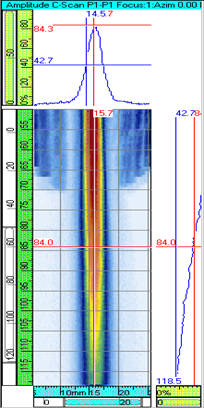
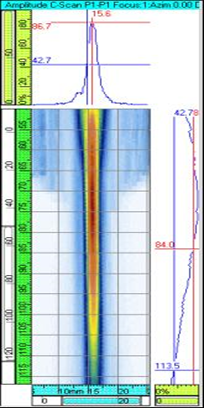
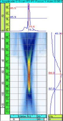
Image displayed in C-Scan . format
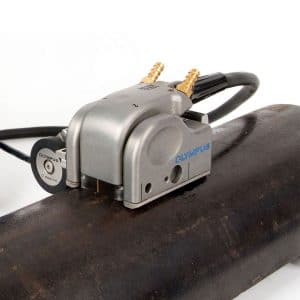
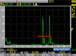
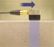
A C-scan is a two-dimensional representation of data displayed as a flat or vertical view of the specimen, similar to a graphical perspective with X-ray images, where The color represents the signal amplitude at each point on the test piece corresponding to the axial position. With conventional instruments, the single element probe must be moved in an xy raster pattern over the test specimen. With a phased array system, the probe is usually physically moved along one axis while the beam sweeps electrons along the other. An Encoder will normally be used where exact geometrical correspondence of the scanned image must be maintained, although timed manual scan modes (exact location not encoded) will be used. can also provide useful information in many cases.
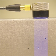
The next images show a C scan image of the reference sample block performed with a conventional embedded ultrasonic inspection system with a converging probe and with a phased array system using an coded hand scanner and tip linear probe. Imaging from a phased array system is done in seconds, while scanning with conventional embedded probes takes minutes.

Normal ultrasonic beam and direction of motion 
Normal ultrasound C-Scan image 
Array ultrasonic beam and direction of motion 
C-Scan image of phased array ultrasound
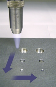
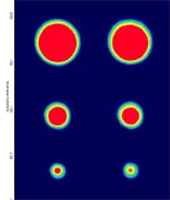
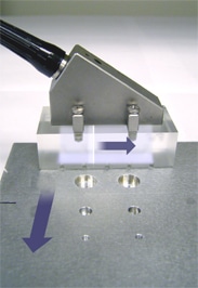
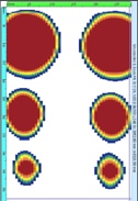
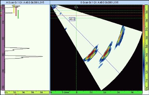
Image displayed in S-Scan . format
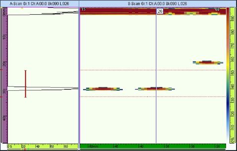
The S scan image represents the cross-sectional mode obtained from a series of scan signals A and has been redrawn with respect to time delay and angle of refraction. The horizontal axis corresponds to the width of the test piece and the vertical axis to the depth. This is the most common format for medical ultrasound as well as for industrial phased array imaging, particularly common in weld inspection.
Applications of Ultrasonic Phased Array Inspection in Industry
Phased array ultrasonic systems can be used in most tests using conventional ultrasonic flaw detectors. Weld testing and crack detection are the most important applications and these tests are performed in many industries including aerospace, energy, petrochemical, construction and pipeline maintenance, Structural metal testing and general manufacturing. Phased array ultrasound can also be effectively used to assess the residual wall thickness of materials in corrosion inspection and surveying applications.
The advantage of phased array ultrasonic inspection technology over conventional UT ultrasound comes from its ability to use multiple elements to direct, focus and scan the beam with a single probe assembly. Sound beam driving, commonly known as fan sweep, can be used to beam beams at different angles, simplifying the inspection of components with complex geometries. The small size of the probe and the ability to scan the beam without moving the probe also aid in inspecting components in situations where mechanical scanning capabilities are limited.
The ability to inspect welds with multiple angles from a single probe greatly increases the probability of detection (POD) the discontinuities. Electronic focusing allows optimization of beam shape and size at the location where defects are expected to appear, thereby further optimizing detection probability and resolution. The ability to focus at multiple depths also improves the ability to size critical defects. Focusing can greatly improve the signal-to-noise ratio in difficult applications, and the multi-group electronic scanning enables rapid production of intuitive C-Scan images.
Advantages of using PAUT . ultrasonic testing
The PAUT ultrasound has a number of advantages over conventional ultrasound transducers, stemming from its ability to control the beam transmitted into the structure under test.
PAUT ultrasound can reduce inspection time by eliminating or reducing the need for mechanical scanning and replacing it with the ability to perform electronic scans. Electronic scanning is performed by activating successive groups of elements in the array probe. Eliminating or reducing mechanical scanning also increases the reliability of the tests.
Whereas a conventional ultrasonic transducer has a fixed focal length and a single angle, a PAUT transducer allows the shape and focal position of the ultrasound beam to be changed to optimize inspection capabilities. Acoustic energy can be concentrated and hysteresis laws can be applied to direct the beam. Dynamic depth-of-field focus allows tests to be performed at multiple depths in the same amount of time compared to conventional probe testing.
The PAUT test also improves the reliability of the tests and ability to judge defect size can be improved.
Due to its versatility, the PAUT transducer can replace many conventional ultrasonic transducers. As a result, it can simplify complex test procedures and reduce the calibration and setup steps involved.
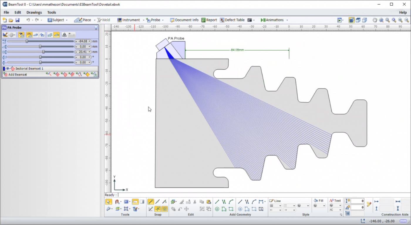
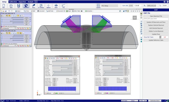
Compared with conventional single-element probe tests, detection and sizing of defects is much easier and more accurate. Instead of having to move the transducer to find the optimal signal that can be obtained from a single transducer, the PAUT probe allows tens of beams to be collected at once. The greatly improved efficiency makes it easier to identify defects and reduces the number of misinterpretations. When used in conjunction with simulation software such as SetupBuilder, ESBeamTool, CIVA, the test plan can be optimized to improve detection. Data logging and traceability are also greatly improved. For example, test data can be saved and compared with simulation results, helping to confirm whether or not there are discontinuities in the tested structure.
Related Posts
Matters needing attention when planning the scan (Scan Plan) in Phased Array and TFM inspection for welds
History of “Scan plan” Scan planning is an indispensable step,...
1 Comments
Apr

Check longitudinal beams and splits in propeller posts with low frequency Phased Array ultrasound
Application The solution uses phased array ultrasound to check the girder cap...
Apr

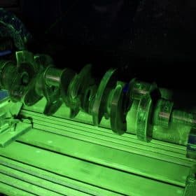
Use Phased Array to check gears on large equipment
Mining and other industries use heavy equipment in...
Jul
Advanced Phased Array inspection for single-sided access welds
Imaging-assisted ultrasound examination methods such as ultra...
Jul
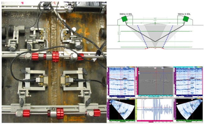
Using the OmniScan ultrasonic inspection PITCH-CATCH (Tandem) device with the Phased Array probe
Tandem or "parallel" ultrasonic testing technique is applied when the angle...
Feb
Resolves transducer and wedge junction problems in Phased Array . testing
In Phased Array ultrasonic testing, inactive elements can...
May

Check the load-bearing pins on the bridge using Phased Array
Many bridges are built using studs that can withstand...
Dec
Ultrasound Phased Array Uses Instead of Radiographic Imaging
Tham khảo: Sử dụng Phased Array với bộ quét Cobra kiểm tra mối hàn ống...
1 Comments
Dec

Eliminate bottlenecks: Analyze and interpret Phased Arrays in seconds
We already know that phased arrays have strong image support...
May
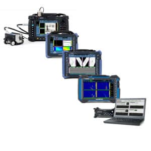
Related equipment in the article
Measure thickness
Corrosion test
Pingback: Solve transducer and wedge junction problems in Phased Array testing – VISCO NDT