


History of “Scan Plan”
Scan planning is an indispensable, but often overlooked step in the Phasing Array (PA) testing process. Proper scan planning leads to reliable test results, higher productivity, and guaranteed repeatability but can often be difficult due to the different nature of PA, TFM techniques applicable to applications. difference.
Scan planning has also been covered a lot in the traditional ultrasound examination, including:
- Evaluation of transducer characteristics, output point, emission angle, beam amplitude...
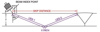
- Determine the probe travel area (skip distance) with the angle probe
- Identify beam overlap when examining UT and needing C-Scan mapping
- Calculating the beam size
What is a scan plan?
Before performing any inspection work Phased Array, TFM good ultrasound AUT come on, one scan option have to be done. This scanning plan should be documented, including information regarding the test strategy to ensure reproducible results. This information will also help a lot in the evaluation and interpretation of the data in the future. When planning a weld inspection, probe placement and execution strategy will be influenced by the following key factors:
- The requirements of the standard (ASME, AWS, API…) for ultrasonic testing and Phased Array
- Material Type, Stainless steel, Duplex Steal, Carbon Steel, Dissimilar Metal…
- Code requirements for coverage with HAZ heat affected zone
- Welding processes being applied (SMAW, SAW, FCAW, etc.)
- Welding bevel design, blunt edge design, general weld configuration
- Limits on weld access, accessible from the outside, inside, one side or both sides of the weld, the width of the weld edge, the shortest possible distance from the probe to the CL.
- There is use ToFD and traditional ultrasound channels?
- Number of devices, scan speed to be achieved, maximum number of scans, data acquisition rate, production speed, etc.
- Type of device to use, upper limit on number of broadcast channels, maximum number of channels (16:128 or 32:128 or 16:64 or 64:128)
- Dimensions assessment requirements, acceptance standard is applying
- The requirements for the defect assessment of the standard are applicable.
- With some standards, the use of linear scan is optional.
Reproducibility of test results
When testing a Phased Array or TFM, the variety of options creates problems with repeatability, stability, and training of project personnel. With the same weld, there can be many ways to plan different scanning plans.
While planning the test, we can have many different options, including
- To scan Sectorial Scanning nice E-Scanning nice Composed Scanning?
- Encoded nice Manual
- Number of variables/Aperture create sound beam
- Number of Groups/Multi-Channel
- Convergence location for each group
- Option transducer frequency, number of variables, type wedge use…
- Considerations about extension of the sound beam
- Angle of transmission, angle of incidence (BEER)
Required information while on Scan Plan
To limit the factors that change too much, in most standards, there are mandatory parameters in the Scan plan, including:
- Details of welds to be checked, weld edges, curved surfaces
- Probe and wedge to use
- Acoustic Beam Convergence Law variants to use, including equipment related settings
- Information about Index Offset
- Number of scans, scan direction
- In the ASME standard, the information is mainly mentioned in Section V Article 4, part MANDATORY APPENDIX IV for manual Phased Array testing and MANDATORY APPENDIX DRAWING for testing Phased Array using position encoder
- In D1.1, the information related to the Scan Plan is located at Part G Testing Procedure under Annex WILL
- In API 1104, Scan Plan related information is included in the Specialized Calibration Requirements procedures

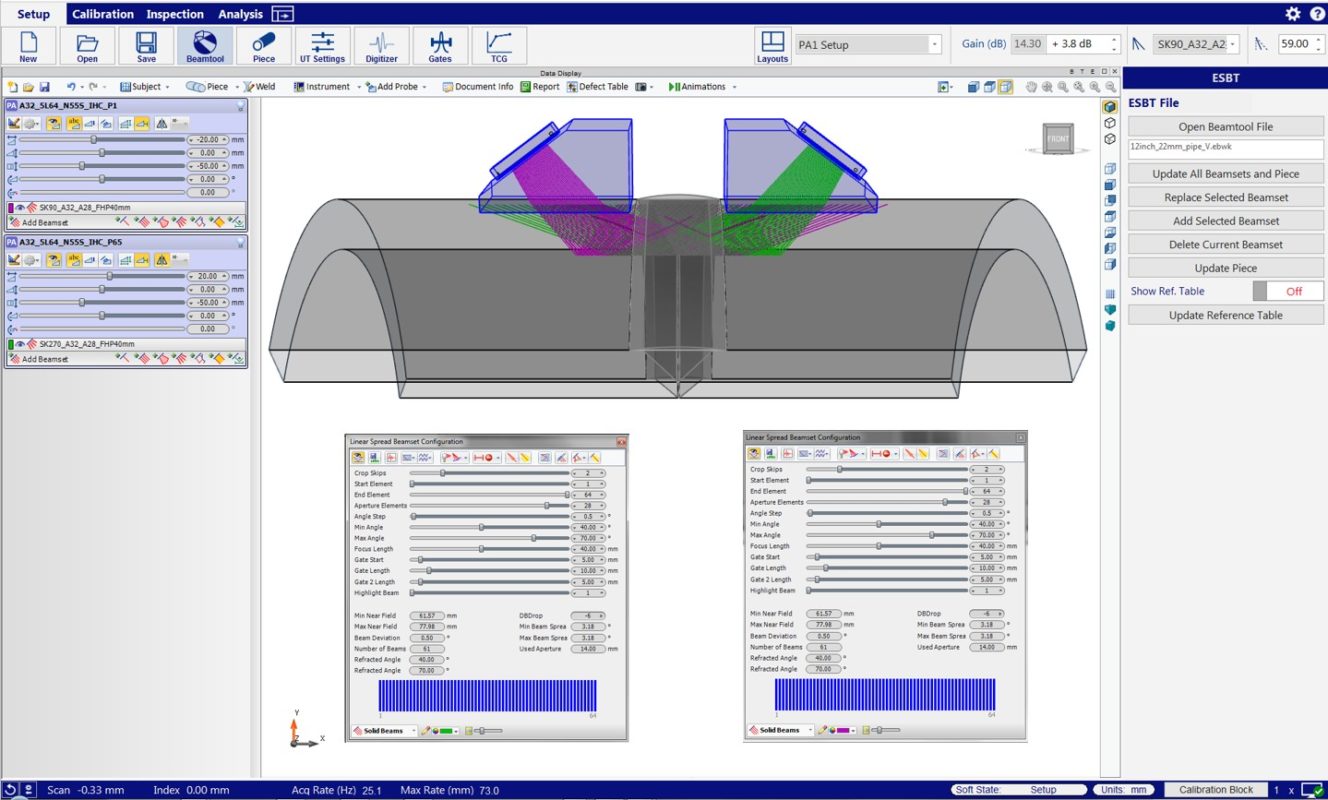
However, in order to develop a test plan, there are usually 3 main parameters: Weld type, Probe selection, wedge and Beam emission rules to be used. This information can be drawn by hand or using specialized software such as ES BeamTool nice Setup Builder.
Scan Plan for TFM . test
When full-matrix/full-focus (FMC/TFM) data acquisition was introduced in the NDT industry a few years ago, it was considered a revolutionary technique for optimizing time and results. test. However, even with recent arrival, some limitations and challenges are made clearer, especially for weld inspection applications.
From selecting probes to performing calibrations, testers need to make important choices to make in order to develop the optimal test strategy that complies with the requirements of the standard.
At the time of writing (2020), the only NDT standard that contains regulations applicable to FMC or TFM is ASME (BPVC). Section V, Article 4 (2019), includes the following appendices:
- Mandatory Appendix XI Full Matrix Capture (FMC)
- Nonmandatory Appendix F Examination of Welds Using Full Matrix Capture (FMC)
- Specific personnel requirements and a training outline in Sec. V, Article 1
When inspecting welds, the scanning plan complies with the code that requires multi-group mode for the following reasons:
- The standard mentions that using only 2T or 2L direct beam is not enough to provide full weld coverage.
- During calibration, line validation requires the use of the through-wall slot, which runs from the top to the bottom of the test specimen.
Typically, testers who are used to working with PAUT try to produce results that correspond to the standard sectorial scan modes using a group of 2T wave sets and doubling the thickness to get the equivalent mode. with 4T. This is not an optimal implementation as this configuration with 2 wave modes cannot detect the entire through-wall slot on the calibration sample.
To achieve code compliance, multigroup configurations need to be used, including self-tandem wave modes such as 3T and 5T. Using a device like the OmniScan X3 can have data from 4 groups simultaneously without affecting Amplitude fidelity and resolution.
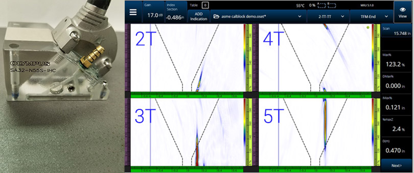
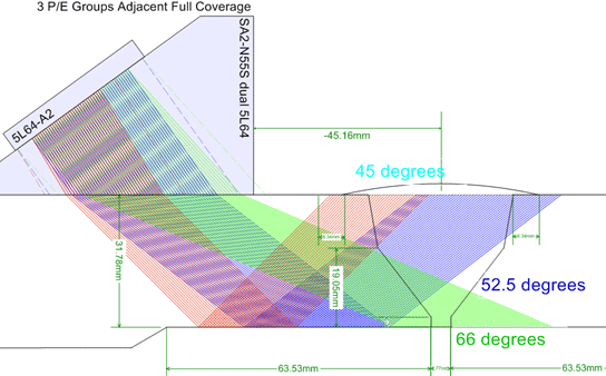
In the image above, with the option of using the 5L64-A32 probe placed on the calibration block sample at the position with the through-wall slot. It can be seen that in order to have good coverage for the entire slot, it is necessary to use 2 additional modes, 3T and 5T self-tandem mode in addition to 2T and 4T modes. Images and data belong to K. Shane Walton (University of Ultrasonics).
Notes when planning the test
- Like PAUT, TFM testing for large thickness welds requires multiple Index offsets to cover the entire weld area.
- Due to the large influence of the thickness difference on the TMF signal, the thickness of the calibration specimen should not exceed ±5% of the thickness of the test specimen.
Pingback: Ultrasound Phased Array used as an alternative to radiography – VISCO NDT