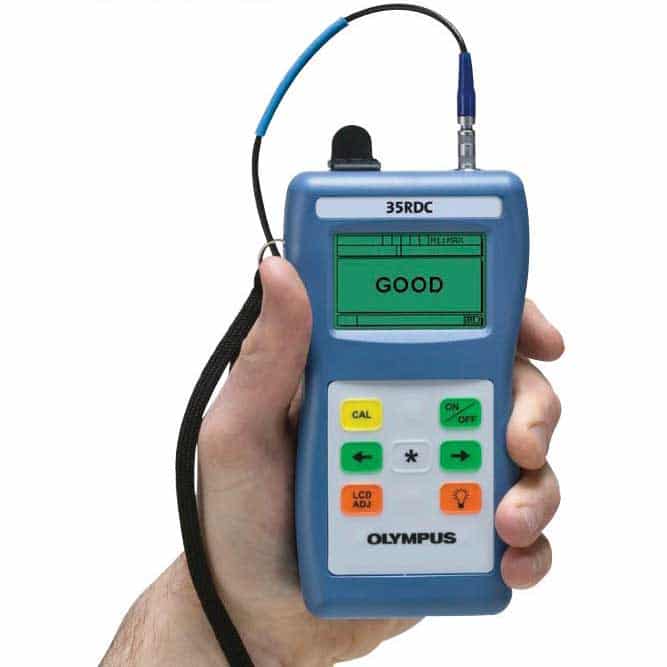
The 35RDC is a simple, go/no-go ultrasonic instrument, created for the inspection of the new aircraft and other composite structures. It was designed to be used by non- NDT-trained personnel to detect subsurface impact damage on solid laminate structures (not honeycomb structures). The concept was developed and then patented by a commercial airline and is based on the well-establish pulse/echo technique. The 35RDC is now referenced in the B787 Structural Repair Data.
Features
- For use on solid laminate structure aerospace composites
- Simple one-button calibration
- Thickness range 0.63 mm to 22.8 mm (0.025 in. to 0.900 in.)
- Simple Good/Bad/Beyond Cal display readout
- Back light matrix display with user help text
- AA battery operation
- Handheld, weighing only 0.24 Kg (8.5 oz.)
- Energy saving Auto Power off feature
- Long battery life, 150 hours typical
- Battery life indicator
Specifications
| General | Environmental IP65 compliant | Splash-proof, impact-resistant case. Sealed, color-coded keypad |
| Operating Temperature Range | -10° C to +50° C (+14° F to 122° F) | |
| Size: (W x L x H) | 84 mm x 152 mm x 84 mm (3.31 in. x 6.0 in. x 1.50 in.) | |
| Weight | 0.24 kg (8.5 oz) | |
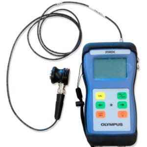
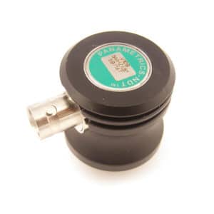
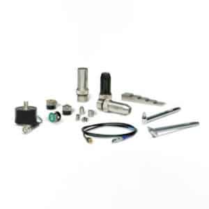
| Standard Inclusions | Wrist strap, 3 AA batteries, 5 MHz transducer, transducer cable, couplant, carrying case, rubber protective boot with neck strap, instruction manual, two-year limited warranty | |
| Display Modes | Digital Readout Good, Bad or Beyond CAL thickness
Advanced user setting shows A-scan or waveform. For use by qualified NDT personnel only. |
|
| Thickness Measurement Range** | 0.63 mm to 22.8 mm (0.025 in. to 0.900 in.) ** Thickness range depends on material, transducer, and surface conditions. |
|
| Material Velocity | Fixed velocity for carbon fiber aerospace composite | |
| Transducer Frequency | 5.0 MHz | |
| Measurement Update Rate | 20 Hz | |
| Deviation alarm set points | Programmable +/- from calibration point. Set in advance setup | |
| Power Supply | Battery | 3 AA alkaline or NiMH batteries |
| Operating Time | 150 hours typical battery life; 30 hours continuous with backlight on | |
| Low Battery Indicator | Continuously indicates battery status | |
| Battery Saver | Auto Power Off/Continuous On | |
| AC Power Supply | Optional |
Ordering information
[U8200066] 35RDC
The Model 35RDC is intended for preliminary screening only. It is not intended to replace comprehensive testing by a trained operator using an ultrasonic flaw detector. When using the 35RDC, users are responsible for making sure they have been trained for any particular inspection and are following the recommended inspection procedures outline in the Service or repair manual provided by the component or aircraft manufacturer.
Included with the equipment:
- 35RDC Gage,
- LCB-74-4 Cable,
- V109-RB,
- MG2/CC Carrying Case,
- MG2/RPC Rubber Boot with Neck Strap,
- 35RDC Manual (English only) 910-268-EN,
- B2 Couplant, and
- (3) AA Alkaline Batteries)
Optional Accessories
- USB/ADP-115: AC-115 power supply
- USB/ADP-230: AC-230 power supply
- B2 Couplant (Spare)
*All specifications are subject to change without notice.
Theory of operation
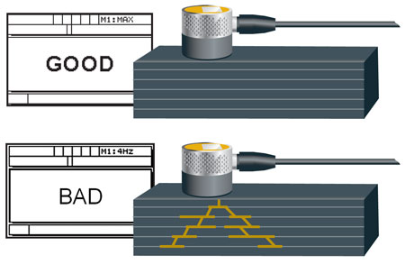
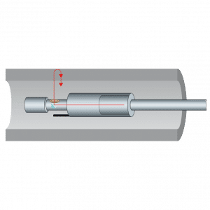
Ultrasonic sound waves travel through materials in a predictable way. When a high-frequency sound pulse generated by an ultrasonic transducer is coupled into a piece of solid laminate composite, it will travel through the material until it encounters an air boundary, at which point it will reflect back as an echo that can be detected by a gauge. In the case of structurally solid composite, that reflection will come from the back wall or the inside surface of the laminate. If, however, there is a delamination or subsurface cracking parallel to the surface, then the reflection will come instead from the damaged area and arrive earlier in time. The difference in the echo patterns from good vs. damaged material can be used to identify areas of internal damage that aren’t visible from the surface.
The default alarm setting for the Model 35RDC will respond to delamination occurring in the composite material within a nominal two-ply thickness buffer zone from the back wall to accommodate for velocity variations, slight thickness variations, or ply drops.
Procedure
The Model 35RDC gauge isn’t intended to scan large areas. Rather, it’s used to screen areas of suspected damage.
The 35RDC gauge must first be calibrated for the specific thickness of material that is to be tested. The user normally identifies an area that shows impact damage and then moves to a point three to six inches (75 to 150 mm) away from this spot to an area that appears to be clean. The ultrasonic transducer is coupled to this known good area of the material and the operator presses a calibration key. The gauge identifies the back wall echo from the far side of the composite at the calibration point and establishes it as a reference. The gauge then switches into test mode and the user may move the transducer to the suspect area.
When the transducer is coupled to a test point, the gauge compares the new echo pattern to the reference pattern. If an echo is received earlier than the back wall echo, or if the back wall echo isn’t present, that indicates probable damage and the gauge displays the indication “bad.” If an echo is received earlier than the calibrated back wall echo window, or if the back wall echo isn’t present, that indicates probable damage and the gauge displays the indication “bad.” If only a strong back wall echo is received within the calibration window, then the gauge displays the indication “good.” If only a strong back wall echo is received, but it’s beyond the calibration window, then the gauge displays the indication as “beyond cal thickness.”
Because this analysis is based on the reference echo, the 35RDC must always be recalibrated whenever switching to an area of different thickness or different material. This calibration procedure normally takes only a few seconds. If an attempt is made to measure material of a different thickness without recalibration, the gauge will display either “bad” or “beyond cal thickness” depending on whether the new material is thinner or thicker than that used for calibration. It’s important to note that a “bad” indication should be investigated further by a trained professional who is familiar with composite inspection with dedicated equipment such as BondMaster 600. Testing with the Model 35RDC gauge is for preliminary screening only and isn’t equivalent to comprehensive testing by a trained inspector.
